Key Components of an Induction Heated Vacuum Furnace
· Induction Coil: Rectangular copper tubing with internal water cooling. It carries medium-frequency alternating current that generates the magnetic field. The coupling gap between the coil and crucible is minimized to maximize heating efficiency.
· Crucible: Positioned concentrically inside the induction coil and used to hold the metal charge. The crucible material is selected based on alloy chemistry and operating temperature (see crucible selection guide below).
· Vacuum Chamber: A double-walled, water-cooled steel vessel sealed with metal O-rings or elastomer seals at all flanges, viewing windows, and feedthrough points. The surface temperature is maintained below 50°C through water cooling.
· Vacuum System: A multi-stage pumping system consisting of a mechanical roughing pump (atmosphere to ~10 Pa), Roots blower (~10 Pa to ~0.1 Pa), and oil diffusion pump (final vacuum down to 7×10⁻³ Pa). Maximum achievable vacuum level is 7×10⁻⁴ Pa.
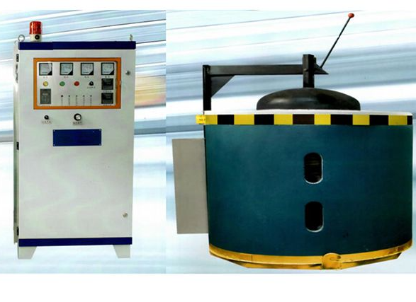
· Furnace Tilting Mechanism: Enables rotation of the furnace body to pour molten metal into molds located below the crucible, either under vacuum or argon backfill conditions.
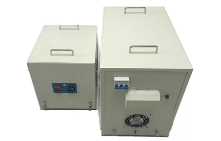
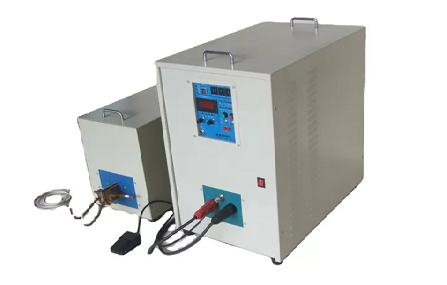
· IGBT Medium-Frequency Power Supply: A solid-state inverter operating at 500–3000 Hz. It provides stepless power control from near zero to full output with efficiency above 92%. IGBT systems are preferred over older KGPS (thyristor-based) power supplies in modern installations.
· Electrical Control System: PLC-based control system with touch-screen HMI. It manages power, temperature, vacuum level, tilt angle, and alloy feeding timing, with full data logging for batch traceability.
· Vacuum-Locked Alloy Feeder: A multi-hopper feeding system (typically 3–5 hoppers) used to add reactive elements such as Al, Ti, B, and Zr into the melt without breaking vacuum conditions.
Induction Heated vs. Resistance Heated Vacuum Furnace
Although both systems operate under vacuum conditions, they are designed for fundamentally different industrial applications. The selection between them primarily depends on whether the process involves melting and casting metals, or performing heat treatment and sintering operations.
| Feature | Induction Heated Vacuum Furnace | Resistance Heated Vacuum Furnace |
|---|
| Heat generation | Eddy currents induced directly in the metal charge | Resistance elements (MoSi₂, graphite, Mo strap) radiate heat to the load |
| Heating rate | Very fast — heat generated inside the metal itself | Slower — heat transferred from element to load surface |
| Temperature uniformity | Excellent in liquid state due to electromagnetic stirring | Excellent across the hot zone for solid loads |
| Efficiency | 80–92% (IGBT power supply) | 60–80% (radiant heat transfer losses) |
| Primary application | Melting, refining, and casting reactive alloys | Heat treatment, sintering, brazing, annealing |
| Electromagnetic stirring | Yes — automatic, contact-free | No |
| Capital cost | Higher | Lower for equivalent hot zone volume |
| Typical max. temperature | Up to 2000°C | Up to 2200°C (graphite element)
|
Operating Temperature Range
Induction heated vacuum furnaces offer a broad operating temperature range, which varies depending on crucible material and coil configuration:
Standard production range: 1000–1700°C — suitable for nickel-based superalloys, cobalt alloys, steels, and stainless steels
Titanium and reactive metals: 1650–1800°C — achievable with zirconia or calcia crucibles to ensure chemical stability
Maximum capability: up to 2000°C — available with customized high-temperature coil systems and optimized furnace design
Key Advantages
| Advantage | Technical Basis | Measurable Result |
|---|
| Oxygen and nitrogen removal | Partial pressure gradient drives dissolved gases out of liquid metal under vacuum | O <20 ppm, N <10 ppm (vs. >100 ppm in air melting) |
| Reactive element control | No atmospheric oxidation of Al, Ti, B, Zr during melting | Ti/Al composition held to ±0.05–0.12% (vs. ±0.3% in air) |
| Volatile impurity removal | Pb, Bi, Sb, Se, Te reach vapor pressure and evaporate under vacuum | Grain-boundary embrittling elements removed — no other process achieves this |
| High thermal efficiency | Heat generated directly in the metal charge by eddy currents | 80–92% efficiency with IGBT power supply |
| Chemical homogeneity | Electromagnetic stirring (pinch effect) circulates the melt continuously | Uniform composition throughout the melt without mechanical stirring |
| Low environmental impact | Sealed vacuum chamber contains all fumes and dust | No combustion gases, no open metal surface emissions
|
Crucible Selection Guide
Crucible selection is the most consequential materials decision in induction heated vacuum furnace operation. An incompatible crucible contaminates the melt in ways the vacuum cannot correct.
| Crucible Material | Max. Temp. | Suitable Alloys | Avoid With |
|---|
| Magnesia (MgO) | >1800°C | Ni-based superalloys, Co-based alloys, steels, Fe-Ni alloys | Alloys with Al >6% |
| Alumina (Al₂O₃) | ~1750°C | Stainless steels, low-Al alloys, Cu alloys | Ti-rich alloys, alloys with Al >4% — Al reduces the crucible wall |
| Zirconia (ZrO₂) | >2000°C | Ti alloys, Co-based alloys, Pt-group metals | High-Si alloys; requires Y₂O₃ or CaO stabilizer |
| Calcia (CaO) | ~1800°C | High-Al titanium alloys, reactive alloys where MgO is marginal | Moisture exposure — hydrates rapidly, must be kept dry |
| Graphite (C) | >2500°C | Cu alloys, precious metals under inert backfill only | Steel, Ni alloys in vacuum — carbon contamination is inevitable
|
Troubleshooting and Maintenance
Melt leakage:
This issue is typically caused by crucible cracking due to thermal shock or incompatibility between the crucible and alloy chemistry. To prevent it, crucibles should always be preheated according to the correct sintering or heating schedule, and material compatibility must be confirmed before processing any new alloy grade.
Slow pump-down or insufficient vacuum:
Begin by inspecting O-ring seals at all chamber flanges, observation windows, and feedthroughs, as even a single worn or damaged seal can significantly increase base pressure. In addition, check the condition of diffusion pump oil and ensure the cold trap is clean and free of contamination.
Inaccurate temperature control:
This is often caused by thermocouple drift, contamination, or improper sensor placement. Regular calibration is essential, and it is also important to ensure the pyrometer sight path through the observation window remains clean and unobstructed.
Routine maintenance checklist:
Regular maintenance should include verifying water cooling system flow rate and temperature stability, checking vacuum pump oil level and quality, cleaning internal chamber surfaces to remove metal spatter after each cycle, inspecting the induction coil for cracks or insulation degradation, and confirming that feeder hopper seals and valve mechanisms are operating correctly.
Frequently Asked Questions
What is the difference between an induction heated vacuum furnace and a vacuum induction melting furnace?
They refer to the same type of equipment. “Induction heated vacuum furnace” emphasizes the heating principle, while “vacuum induction melting (VIM) furnace” highlights the primary application. Both describe a sealed, evacuated system that uses electromagnetic induction to melt metals under controlled vacuum conditions.
What metals can be melted in an induction heated vacuum furnace?
It is suitable for a wide range of high-performance and reactive alloys, including nickel-based and cobalt-based superalloys, maraging steels, premium tool steels, stainless steels, titanium alloys, zirconium alloys, rare-earth permanent magnet materials (such as NdFeB and SmCo), and other specialty alloys. Materials containing elements like Al, Ti, B, Zr, or Nb—which oxidize rapidly in air—particularly benefit from vacuum induction melting to ensure high purity and precise composition control.
What vacuum level is required?
Most standard alloy processing is conducted at approximately 7×10⁻³ Pa working vacuum. For reactive metals such as titanium and zirconium, as well as critical aerospace-grade applications, vacuum levels of 10⁻⁴ Pa or better are typically required. Modern systems can achieve ultimate vacuum levels down to around 7×10⁻⁴ Pa using a combination of mechanical pumps, Roots blowers, and diffusion pumps.
What is the difference between IGBT and KGPS power supplies?
IGBT (Insulated Gate Bipolar Transistor) solid-state inverters provide precise, stepless power regulation from near-zero to full output, high efficiency (over 92%), and accurate frequency control. KGPS (thyristor-based systems) represent older technology, offering more limited control and lower efficiency. For new installations, IGBT power supplies are generally recommended.
How do I choose the right crucible?
Crucible selection should match alloy chemistry. Magnesia (MgO) is commonly used for nickel-based superalloys and steels. Alumina (Al₂O₃) is suitable for stainless steels and low-aluminum alloys but should not be used when aluminum content exceeds 4%. Zirconia (ZrO₂) is recommended for titanium and high-temperature reactive melts. Calcia (CaO) is used for high-aluminum titanium alloys. Graphite crucibles are limited to copper alloys under inert backfill conditions and must not be used in vacuum for steel or nickel-based materials.
How long does a melt cycle take?
A typical production cycle for a 25–100 kg charge takes approximately 2–4 hours, including 30–60 minutes for evacuation, 30–90 minutes for melting and refining, 15–30 minutes for alloy adjustment, and 10–20 minutes for casting and cooling. Larger systems with capacities from 300 kg to 1 ton generally require 3–6 hours per complete cycle.